The purpose of this blog is to expressly outline Phius’ guidelines for the use of constant air volume devices (often referred to as CAR dampers) within outdoor air ventilation systems for buildings pursuing Phius Certification.
Phius published a general memo on outdoor air mechanical systems (via the updated Phius 2024 Guidebook) in September of 2025. The ensuing excerpt from that memo, written by Phius Certification Program Director James Ortega, covers the specific guidelines that govern the performance verification of constant air volume devices. This memo represents Phius’ research-backed guidelines for the use of constant air volume devices. These guidelines are based on extensive field experience gained from project teams and are not discretionary.
In combination, the memo and this blog provide consistent guidance to project teams and ensure the success of Phius projects throughout the design and final certification review processes.
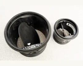
Image courtesy of Steven Winter Associates
Memo Excerpt
AIRFLOW RATES AT INDIVIDUAL REGISTERS
Supply Air Flows
Airflow measurements must be taken per ANSI/RESNET/ICC Standard 380-2022.
Measured supply air flow rates must meet the design intent within allowable tolerances.
Supply Airflows per register must be +/-5 cfm or +/-20% of the design rate (whichever is greater) as per Phius' revised tolerances.
If measured supply air flows are found to be out of the tolerances described above, but meet all applicable requirements for ASHRAE 62.1, 62.2, and/or mechanical code and co-requisite programs, the Mechanical Design Engineer of Record may sign off using either option a. or b. below:
a. Direct sign-off approving the measured airflows.
b. Where constant air volume devices (also known as CAR Dampers) are installed, verification of the following items per Addendum A: 6.6.1 below is required:
Static pressure limits are within manufacturer tolerances for damper operation.
The direction of the damper is correct.
Ducts are sealed.
Exhaust Air Flows
Airflow measurements must be taken per ANSI/RESNET/ICC Standard 380-2022.
Measured exhaust air flow rates must meet the design intent within allowable tolerances.
Exhaust airflows per register must be +/-5 cfm or +/-20% of the design rate (whichever is greater) as per Phius' revised tolerances.
Exception 1: Bathrooms with continuous exhaust systems (and no intermittent direct exhaust fan) are required to provide >= 20 cfm of exhaust regardless of the tolerances noted above.
Exception 2: Kitchens with continuous exhaust systems (and no intermittent direct exhaust range hood) are required to provide >= 25 cfm of exhaust regardless of the tolerances noted above.
If measured exhaust air flows are found to be out of the tolerances described above, but meet all applicable requirements for ASHRAE 62.1, 62.2, and/or mechanical code and co-requisite programs, the Mechanical Design Engineer of Record may sign off using either option a. or b. below:
a. Direct sign-off approving the measured airflows.
b. Where constant air volume devices (also known as CAR Dampers) are installed, verification of the following items per Addendum A: 6.6.1 below is required:
Static pressure limits are within manufacturer tolerances for damper operation.
The direction of the damper is correct.
Ducts are sealed. In accordance with Energy Star requirements.
Addendum A
Language proposed to RESNET from Anthony Lisanti & Michael Browne reviewed and approved for submission by the Phius Technical Committee on December 11th, 2024.
3.X Definition
Constant Air Volume Device: TBD
A balancing damper placed inside a duct in order to obtain a constant flow within a certain pressure range.
6.6 Verification for Constant Air Volume Devices
If by Testing and Balancing (TAB) contractor, then the Rater/Verifier shall verify a sample via RESNET Sampling Protocol for HERS Rating, or per Phius Sampling requirements if not for a HERS Rating.
6.6.1 Installation Conditions
Proper design and installation of the appropriate constant air volume device shall first be confirmed for 100% of the registers by a TAB contractor or Rater/Verifier.
The design airflow capacity and if adjustable, the air flow setting of the constant air volume device for desired air flow shall be confirmed.
The installed orientation of the constant air volume device for the direction of airflow desired shall be confirmed.
Check that operation is such that the constant air volume device is not fully open or fully closed and is able to move freely.
In duct static pressure measurement of the constant air volume device shall be measured and recorded and/or airflow volume using the method described in Section 6.4. The pressure measurement shall be made within the branch duct ahead of the Device location. For example, in the supply branch upstream, ahead of the Device, or in the exhaust duct downstream of the Device.
The static pressure measurement shall be compared to the pressure range and design airflow required by the manufacturer for the constant air volume device installed.
The system static pressure delivered to the main trunk shall be verified to ensure it is within the acceptable range as required by the constant air volume device manufacturer.
After the above conditions have been met, the airflow at the inlet or outlet can be measured by any of the methods listed above in Section 6.6. [May be verified by sampling per RESNET or Phius as appropriate]
6.6.2 Procedure to measure airflow at inlet or outlet terminal with Constant Air Volume Devices
This section defines procedures to measure the airflow of a mechanical ventilation system at an inlet or outlet terminal using a constant air volume regulator or damper, often referred to as a constant airflow regulator or CAR Damper. The airflow shall be measured using one of the following:
a powered flow hood with an external hood (Section 6.2.1),
a vane anemometer with hood and flow straightener (Section 6.3.3),
Bag Inflation Device (Section 6.3.2), or
midstream in the Ventilation Duct (Section 6.4), after the Installation Conditions are met.
Informative note: Preferred Methods
Powered flow hoods and Vane anemometers shall be provided with a hood, tent, or flow straightening device of sufficient size so as not to create additional static pressure or backpressure on the constant air flow device, thereby causing it to adjust flow based on the measurement device.
View the full memo covering Phius’ on-site verification protocol for outdoor air ventilation systems here.